Michigan Tech Volcanic Clouds Workshop:
The Total Ozone Mapping Spectrometer (TOMS)
Objectives
Learn about the TOMS data products and some of the key retrieval capabilities.
Understand how sulfur dioxide emission masses are derived from TOMS data.
Examine the range of eruption types observed by TOMS, and compare the results of ultraviolet retrievals to infrared retrievals.
Introduction
NASA's Nimbus-7 satellite was launched in 1978 carrying the Total Ozone Mapping Spectrometer (TOMS). The TOMS instrument was designed to measure column ozone amounts on a global scale to monitor trends in ozone formation and destruction. In 1982, unusually high ozone amounts were discovered in the data over Mexico after the eruption of El Chichon. Sulfur dioxide (SO2) was found to be the interfering species causing the anomalous values. Scientists and engineers were then able to determine how to separate ozone and SO2 signals, and calculate the amounts of SO2 erupted from volcanoes. TOMS instruments have been operating on almost a continual basis since that time (Table 1).
Table 1. Available TOMS Data, 1978 - Present
|
Platform |
Start of Data |
End of Data |
Nadir Footprint |
|---|---|---|---|
|
Nimbus-7 |
November 1, 1978 |
May 6, 1993 |
50 km |
|
Meteor-3 |
August 22, 1991 |
September 27, 1994 |
62 km |
|
Earth Probe |
July 17, 1996 |
Current |
24 km (launch - Dec 1997) 39 km (Dec 1997 - present) |
|
ADEOS |
September 11, 1996 |
June 29, 1997 |
42 km |
The TOMS instruments measure solar irradiance, and the radiance reflected by the Earth's surface and backscattered by the Earth's atmosphere. They use six wavelength bands in the ultraviolet spectrum, and thus measurements are restricted to daylight hours. The wavelengths have changed slightly with the different instruments, but the Earth Probe parameters (in nm) are: 308.6, 312.6, 317.6, 322.4, 331.3, and 360.4.
In most cases, TOMS data provide full sunlit Earth coverage once per day; orbit overlap at high latitudes sometimes provides additional coverage. Most eruptions can be observed for only a few days before they become indistinguishable from background. The largest eruptions observed by TOMS, such as the 1991 eruption of Mt. Pinatubo, can be tracked for weeks.
We use IDL software to manipulate, display, and analyze TOMS data. The full archive of data is stored at NASA Goddard; for our research at MTU we have subsets of TOMS data. The software we have developed over many years of TOMS analyses is "scientific" rather than "professional"; so there is the potential for crashes and such.
This exercise contains three parts:
-I, Introduction to the TOMS Data Products;
-II, Sulfur Dioxide Mass Retrievals; and
-III, Case Studies.
The case studies include a variety of volcanic eruption types and scientific/hazards applications of the different TOMS data products. A list of relevant publications and sources of information is included at the end of the exercises.
I. An Introduction to the TOMS Data Products
For commands that you need to type or key buttons, I will put them in bold.
Discussion of background information and features of the data are in italics.
Only the left mouse button is used for making selections.
The tutorial starts at the point where you have:
-logged onto a UNIX workstation at MTU.
-have opened up an x-terminal
-have moved to the directory which contains the TOMS-plotting program.
Let's start with a look at the April 4 eruption of El Chichon, Mexico in 1982. From Table 1 above, you can see that this eruption occurred while the Nimbus-7 TOMS was operating.
To start the TOMS data plotting software, type tplot_working and hit Return.
-A window appears with satellite options - choose Nimbus-7.
-An "Enter File Type" window appears - choose Level-2 daily file.
In the Data file menu box, select year 1982 (double-click on 1982). The files which appear have coded names: s82001.n7t, s82002.n7t, and so on. The "82" refers to the year, the 001 refers to the "Julian day" (each day of the year has its own number, from 0 to 365), and "n7t refers to "Nimbus-7 TOMS". We want to look at April 4, so scroll down and select the file s82094.n7t (double click).
The "More Data" window appears (may take a little time) - select Continue.
Ia. TOMS Ozone Product
The "Main Menu" appears - select Edit Display Parameters.
A new window appears - select Change Variable.
A new window appears - select Ozone, then v7.
On the Main Menu, select Display. Move your cursor into the Display window to get the true colors, and watch how the orbital data are being plotted.
This gives you a color ozone map of the world for April 4, 1982 overlain on continental outlines. Note the trends in the ozone levels, and the Northern Hemisphere structures, showing several lobes of high ozone extending from the polar region southwards. The main data product of the TOMS instrument is "total column" ozone. The TOMS data production algorithm assumes that ozone is the only absorber present in the atmosphere, and uses a Rayleigh scattering, radiative transfer model. The model calculates backscattered radiances as a function of total ozone, latitude, viewing geometry, and surface reflectivity (albedo). Ozone is derived by comparing measured to theoretical radiances. The scale is in Dobson Units, a measure of the ozone concentration in a hypothetical column (volume) of atmosphere between the satellite and the reflecting surface (Earth).
Ib. The Zoom Function
To zoom in to central Mexico (El Chichon is 17N latitude, 93W longitude), select Zoom Function.
A new window appears, and select Mouse ROI Define (ROI is Region of Interest). The window will go away. The next step will be to use the mouse to define the zoom-in region.
Notice that there is a dotted-line grid on the map with latitude and longitude labeled; the grid boxes are 30 degrees altitude and longitude. Click on a point at 0 latitude, -120 longitude - this will define the lower left corner of your zoomed box. Click on about 45 latitude, -60 longitude (you don't have to be exact). A box will appear on the map showing the selection outline.
The Main Menu reappears - if you don't like your box parameters, hit Zoom Function and redo it. If you are satisfied, select Display and the map will redraw. Whenever you want to return to the Full-Earth view, just hit Zoom out to max.
Label El Chichon on the map:
On "Main Menu", select Edit Display Parameters.
A new window appears - select Label Volcano.
Your x-term window appears - choose "select from list" by typing s and hit return.
Type 4 for El Chichon, and hit return.
On "Main Menu", select Display to see a small filled triangle marking the volcano position. Now you see the ozone anomaly pretty much as it was first observed by NASA scientists.
Ic. TOMS Reflectivity Product
The "Main Menu" appears - select Edit Display Parameters.
A new window appears - select Change Variable.
A new window appears - select Reflectivity.
On the Main Menu, select Display.
The longest wavelength (360 nm) of the TOMS instruments is not sensitive to ozone or SO2, and can be used to look at Earth albedo, or reflectance. In practice, the reflectivity allows us to look at high atmospheric clouds. You can see evidence of weather systems, for example an arc-shaped bank of clouds off of the East coast of the United States. The scale gives percentage reflectance.
Id. TOMS Sulfur Dioxide Product
On the "Main Menu" - select Edit Display Parameters.
A new window appears - select Change Variable.
A new window appears - select Sulfur Dioxide - select v7.
On the Main Menu, select Display.
The "v7" refers to a production algorithm, which is not adequate for analysis. Later we will use a more robust algorithm for retrieving SO2 masses. The TOMS instrument measurements of the backscattered radiance are determined by scattering of air molecules and aerosols, surface and cloud reflections, and absorptions by ozone and sulfur dioxide. Background sulfur dioxide levels are essentially zero, so under normal conditions ozone structure is mapped by TOMS. However, when significant amounts of sulfur dioxide are emitted by volcanic eruptions, these can be detected by TOMS. The SO2 scale is also in Dobson Units (gas volume per hypothetical column), which can be readily converted to SO2 mass.
Ie. TOMS Aerosol Index Product
On the "Main Menu" - select Edit Display Parameters.
A new window appears - select Change Variable.
A new window appears - select Aerosol Index.
On the Main Menu, select Display.
The TOMS aerosol index (AI) algorithm is defined as the difference between measured and calculated values at the 331 nm band, for the Earth Probe instrument. For "clear" sky and water clouds the AI is typically near zero. Absorbing aerosols from smoke and dust, such as volcanic silicates, produce positive AI values. AI values become increasingly positive with increases in aerosol absorption optical depth and cloud altitude. Non-absorbing aerosols, such as those from sulfate particles, produce negative AI values, typically of smaller magnitudes. Thus, volcanic ash and sulfate aerosols can be observed with TOMS over land, water, or tropospheric clouds. The scale is a relative one, with no dimensional units.
II. Sulfur Dioxide Mass Retrievals
The mass retrieval technique is relatively straightforward, although in practice each eruption presents a different set of conditions and obstacles. Here we'll work through the basic procedure, using the major eruption of Mt. St. Helens in Washington State on May 18, 1980, again during the Nimbus-7 TOMS period.
First, let's return to the full Earth view: from the "Main Menu", select Zoom Function, then Zoom out to max. (If you are still in "Aerosol Index" mode, select "Display" from the Main Menu, take a look at the Saharan dust storms.)
On the Main Menu, select Load Related Data.
An "Enter File Type" window appears - choose Level-2 daily file.
In the Data file menu box, select year 1980, scroll down and select the file s80139.n7t.
The "More Data" window appears - select Continue.
On the "Main Menu", select Edit Display Parameters.
A new window appears - select Change Variable.
A new window appears - select Sulfur Dioxide - select v7.
On the Main Menu, select Display.
Zoom in to SW Washington (Mt. St. Helens is 46N latitude, 122W longitude). Select Zoom Function, then Mouse ROI Define. Click on a point at 30N, -150 (W latitude). Click on about 60N, -90 (don't have to be exact). A box will appear showing the outline.
The Main Menu reappears - select Display.
IIa. Locate Mt. St. Helens on the map
On "Main Menu", select Edit Display Parameters, then select Label Volcano.
Your x-term window prompts: choose "label volcano" by typing l and hit return.
Enter: 46, -122, and hit Return.
On Main Menu, select Display to see a small filled triangle marking the volcano position.
You can see there are several pixels with high SO2 located near the volcano. The first step is to replot the data using the iterative algorithm, which provides the best SO2 retrievals.
Select Analyse Data.
Select Mouse define ROI.
Select the lower left point at 40, -140 and the upper right point at 55, -105.
Select Change Algorithm - Version 6a.
Select channels 1234 (default) by clicking on OK. It will take at least a few minutes to calculate.
The wavelengths used by the TOMS retrieval algorithms can be varied to optimize retrievals for each satellite sensor. For Nimbus-7 and Meteor-3 TOMS, the shortest 4 wavelengths give the best results. However, Earth Probe TOMS has a different wavelength configuration, and channels 2, 3, 4 and 6 are used to retrieve SO2.
When the Analysis Menu returns, choose Return to Main Menu.
Select Edit Display Parameters.
Select Change Variable - Sulfur dioxide - V6i.
Since you calculated only a subset of data from your original image, only those data will appear. Use the Zoom Function to zoom in around your data set (40, -140 and 55, -105).
Let's also change the scale. On the Main Menu, select Edit Display Parameters.
Select Change Scale.
An enter value window appears - keep the "min" at 0, but change the "max" to 40. Hit OK.
Select Display.
Now you should have a subset of the orbit data on your screen. Most of the pixels have a value around 10. Why? There should be "zero" SO2 in the atmosphere, but the TOMS sensor has a positive bias, but you may also notice that the background is variable, which gives you an idea of the variation of the "zero SO2" level from TOMS data.
In the image you can see the change in pixel size depending on where in the orbital swath. Each orbit contains 35 pixels, 17 to each side of the nadir position. The dimensions at nadir are 50 x 50 km squares (see Table 1), but as you get to outer positions the dimensions become more diamond-shaped, and about 250 km on a side due to the viewing geometry of the TOMS aperture as well as the curvature of the Earth. Notice also the path of the orbit with respect to north-south.
Change the scale to highlight the SO2 cloud better, changing the minimum to 10, and keep the maximum at 40.
Select Analyse Data.
There are three methods we currently use to analyze SO2 clouds.
(1) Pixel: This method simply uses the footprint of each pixel, and sums up the total mass and areas of these within a selected region of interest. You get a separate value for "scan" (pixels) area, and "total" (geographic) area. Due to regions of both overlap and gaps, the two will not be the same. This method is the most straightforward, and particularly useful when there are only a few data points.
(2) Grid: This breaks up the region into a 0.5 km (can be varied) grid cells, and uses a nearest neighbor method to assign a value to each grid cell. This usually uses the available data in the most statistically valid way, and also works well in areas where scans overlap each other.
(3) 2-Dimensional Interpolation: This method uses a contouring method, assigning the available data as points in the center of each pixel. This is useful when there are many points, or when there are gaps in data. This is an experimental feature; it is only used for larger (>10 pixel) clouds. If you select a very large area (like a 30 by 30 degree box) it may take a minute or two to finish.
The basic mass retrieval technique is to calculate how much SO2 is in the cloud, then select some representative areas of background to remove the background bias. The way we select an area to calculate is the same as for selecting a region of interest, by drawing a box around it.
Select Mouse define ROI. Click the mouse on lower left and upper right corners to define a box that contains the SO2 pixels. If you don't like your box, just redo it. Note that the boxes only draw on whole number values of latitude and longitudes. Try to keep the box as close to the cloud pixels, but don't overlap them - remember that the actual cloud boundaries may extend past the TOMS-defined pixel footprints.
Select Tonnage (pixel).
Select direct tonnage from scans.
The results will appear in your x-term (not an IDL window). Write them in the table below.
Table 2. SO2 Cloud calculations
|
|
Pixel |
Grid |
2D_Int |
|---|---|---|---|
|
Cloud box mass (t) |
|
|
|
|
Cloud box area* (km2) |
|
|
|
|
Background 1 mass |
|
|
|
|
Background 1 area* |
|
|
|
|
Background 2 mass |
|
|
|
|
Background 2 area* |
|
|
|
|
|
|
|
|
|
Total cloud mass (t) |
|
|
|
|
|
|
|
|
*use total area values, not total from scans
Select return to previous menu.
Select Tonnage (grid) then tonnage from gridded data. Return to previous menu.
Repeat the process for Tonnage (2D_Int), and tonnage from volume. Return to previous menu.
Now define a background box. Because of the scan position bias, we create a background box which contains roughly the same scan positions, adjacent to the cloud box. It's easier to show than explain (see Figure 1). Repeat the mass and area calculations using all three methods.
To calculate the total cloud mass corrected for background, use the following equation:
cloud mass (corrected) = cloud mass - cloud area * [(back1 mass/area + back2 mass/area)/2]
If you make these calculations, you can see for this example the three methods do not differ by more than 20%. The grid method is used most often for cloud analyses, although we are still studying the effectiveness of each method.
From individual cloud masses, we then aim to calculate an emission tonnage. When possible, a series of mass retrievals are done on subsequent days to derive a decay curve (mass versus time; see Figure 2). Assuming an instantaneous emission of SO2, and that the removal rate is a continuous function of chemical and physical processes, an exponential decay rate can be derived and used to approximate the "original" amount of SO2.
In practice, this is rarely the case. In fact, in many instances we have noticed small, but significant (10-20%) increase in SO2 on subsequent days, before decay occurs. This is difficult to prove using TOMS data alone, as it may be due to method error, emission of H2S converting to SO2, sensor apparent saturation by very thick or concentrated clouds, interference by co-emitted ash, adsorption and desorption of gas from ash surfaces, temporary removal of SO2 by incorporation in ice, combinations of these processes or another process altogether.
III. Case Studies
Here I'll cut you loose to look at eruptions with various interesting features. You are welcome to search the TOMS database at MTU for any eruption of interest. We have data corresponding to the Smithsonian Institution's compilation of volcanic activity, and you can also see all of the TOMS-observed eruptions at the NASA TOMS SO2 web page, at http://skye.gsfc.nasa.gov/.
In Appendix 1 all of the eruptions below, including many others, are listed with eruption dates (plus Julian dates), and geographic positions. In Appendix 2a: Non-Leap Years and Appendix 2b: Leap Years I've added Julian date calendars to help you locate datafiles corresponding to eruption dates for eruptions not in Appendix 1. One more analytical tool which you will find useful is the ability to open up more than one display window:
On the Main Menu, select New Window. A new window, labeled IDL 1 appears. Select Edit Open Window, and specify 1, then hit OK. Then you can use the Main Menu options (Edit Display Parameters - Change Variable) to display another feature, for example if you want to compare SO2 and AI. To close the new window when you're done, place the cursor at the top window bar, click the RIGHT mouse button, and select Close (the last menu option).
Note: When you want to load data for a different eruption, which was observed by a different satellite, you'll find that your "Enter File Type" box will not have any files listed. Hit Cancel, and a box will appear asking if you want to change satellites. Select Change satellite, then pick the appropriate satellite for the eruption of interest, and the files will then appear. (Occasionally this crashes the program. Just restart if that happens.)
IIIa. Large, explosive eruption (Mt. Pinatubo, Philippines)
One of the most useful aspects of the TOMS data is the ability to look at very large eruptions, which could not be adequately studied except by satellite methods. The largest eruption observed by TOMS is the 1991 eruption of Pinatubo. After some precursory explosions, the main eruptive event took place June 15, and was observed by TOMS June 16, and for several weeks afterwards.
You'll see that much of the data are saturated using the v7 algorithm, so to observe the full SO2 range you'll need to recalculate with the "iterative" algorithm (v6a). When you select a region of interest to recalculate with v6a, keep it as small as you can - it can take many minutes to calculate large areas (e.g., >20 by 20 degrees).
Dates/features to look for (Julian date):
June 15, 1991 (166): shows sizable pre-cursory eruption SO2 and ash clouds, drifting about 1500 km to the SW.
June 16, 1991 (167): the clouds from the cataclysmic eruption; due to an unfortunate loss of data transmission for a few scans, the top portion of the cloud was not visible. Reconstruction of this cloud is underway.
June 17-20, 1991 (168-171): SO2 cloud drifts westward and expands
IIIb. Small, explosive eruption (Soufriere Hills Volcano, Montserrat)
Although the larger eruptions are more easily distinguished by TOMS, the sensor has also detected a number of smaller eruptions. In fact, TOMS routinely measures SO2 masses down to a few kilotonnes. Here is an small eruption example from Montserrat, in 1997 seen by Earth Probe TOMS. Known as the "Boxing Day" eruption, this was a relatively small event but was tracked by TOMS as it drifted away from the island. You'll notice that the Earth Probe coverage is less than that of Nimbus-7, and unfortunately this resulted in missing a portion of the SO2 cloud.
Dates/features to look for:
December 26, 1997 (360): This eruption cloud became elongated due to wind shear, which allowed us to identify higher and lower portions of the cloud (portions > 10 km altitude drifted the furthest, < 8 km remained near the volcano). Note also the different extents of the SO2 and ash clouds.
December 27, 1997 (361): the cloud is below TOMS detection just 24 hours later.
IIIc. Large, effusive eruption (Nyamuragira, Republic of Congo)
Effusive eruptions present a different type of problem in SO2 analysis, because of the basic nature of the emission type. Whereas an explosive event might be considered to be essentially instantaneous emission of sulfur dioxide, effusive eruptions from many non-arc volcanoes produce emissions at very high rates which last for days to weeks. One of the most prolific volcanoes in that sense would be Nyamuragira volcano, in the Republic of Congo. Nyamuragira has erupted roughly every other year since 1980, the most recent occurring in early 2001.
Dates/features to look for (Julian date):
December 27, 1981 (361): a large cloud is over the volcano, and drifting NE.
December 28, 1981 (362): the next day, more SO2 has been emitted, and now can be seen drifting more to the N. But, since the cloud is still over the volcano, it becomes very difficult to tell how much "new" SO2 has been emitted.
December 28, 1981 (363 - 365): continuation of large SO2 emissions. This cloud was lost to TOMS detection within a few days, but evidence of the emissions was much later detected by other instruments, and puzzled scientists until TOMS was able to pinpoint the origin to Nyamuragira.
IIId. Small, effusive eruption (Mauna Loa, Hawaii)
A much smaller version of this occurred in 1984, with an eruption of Mauna Loa. The cloud changed drift directions, but remained largely "attached" to the volcano.
Dates/features to look for:
March 25-28, 1984 (85 - 88): observe the daily shifts in wind direction, all of which stretches out the SO2 cloud, yet the "attachment" of the cloud to the volcano area demonstrates emission is somewhat continuous over this time.
IIIe. Atmospheric transport (Cerro Hudson, Chile)
With the use of the Aerosol Index, it has been possible to observe both gas and ash clouds using the same instrument. What we've been finding is that in many cases the gas and ash form distinct cloud masses, that end up drifting in different directions due to changes in wind directions with altitude. The eruption of Cerro Hudson, although overshadowed by the Pinatubo eruption two months earlier,was unusual as it demonstrated clearly the circumpolar transport processes of the upper atmosphere - essentially a huge tracer experiment.
Dates/features to look for:
August 15-21, 1991 (227-233): watch the clockwise drift of the clouds around the south pole, showing a somewhat tortuous path due to variations in the polar vortex. Try changing the projection (Main Menu - Edit Display Parameters - Change Projection - (S)outh Polar Stereographic Plot) to give a better perspective of the transport. When you want to continue and use the default projection, it's fastest just to restart (Main Menu - Restart).
IIIf. SO2-ash separation (Nevado del Ruiz, Colombia)
This was a relatively small, but SO2-rich eruption. A pre-cursory event was detected by TOMS on September 11, 1985, but the main eruption occurred two months later. We have noticed that many eruptions exhibit a separation of gas and ash species. If the separation occurred well after the eruption, it might be attributable to gravitational settling. However, many of these separation events appear to reflect a separation prior to or during the buoyant plume rise, suggesting atmospheric or volcanological processes.
Dates/features to look for:
November 14-16, 1985 (318-320): the previous day's eruption cloud can be observed. Note the striking difference in configuration and position of the SO2 versus ash clouds (open up a second window and display the AI). By the following day the ash cloud is no longer discernible (which may also be due to missing data in the region), but the SO2 cloud can be observed.
IIIg. SO2-ash coincidence (Mt. Spurr, Alaska)
While separation is often observed, cloud coincidence has also been noted. In this case the clouds remained coincident for several days following the eruption. Use a zoom which includes the upper North American continent, so you observe the daily movement of the clouds. It may help to add the U.S. State outlines (Main Menu-Edit Display Parameters-USA States).
Dates/features to look for:
September 17-20, 1992 (261-264): track the SO2 and ash clouds as they drift from Alaska to North Dakota, over Toronto, Canada and towards the tip of Greenland. Note that even when the cloud is sheared, the two species remain coincident, indicating that they are well mixed vertically.
IIIh. Sulfate detection (Hekla, Iceland)
The AI has the potential to observe sulfate aerosols, as noted earlier. In the case of the 2000 Hekla eruption, a distinct aerosol cloud was observed by Earth Probe TOMS. Note that the AI gives negative values for sulfate, reflecting the effects of absorbing aerosols. The sulfate aerosol cloud stands out better if you change the AI scale slightly (Main Menu - Edit Display Parameters - Change Scale), changing the minimum to -5, and keeping the maximum to 10.
Dates/features to look for:
February 27-29, 2000 (58-60): compare the SO2 and AI images. The SO2 cloud is visible for several days following the eruption, but the sulfate aerosols are only easily detectable on the 27th. An unfortunate glitch in the data processing cuts off the high latitude datapoints in the version 7 SO2 images, but you can see the data if you reprocess them in the iterative algorithm (V6i).
For February 27, try looking at just one orbit at a time:
Select Load Related Data - ORBIT from level-2 daily file - 2000 - choose the daily file for day 58 - from the list, select s19683.
A new window appears with the file on it as your only choice. Click on that. Then once the file is loaded, Display it as always.
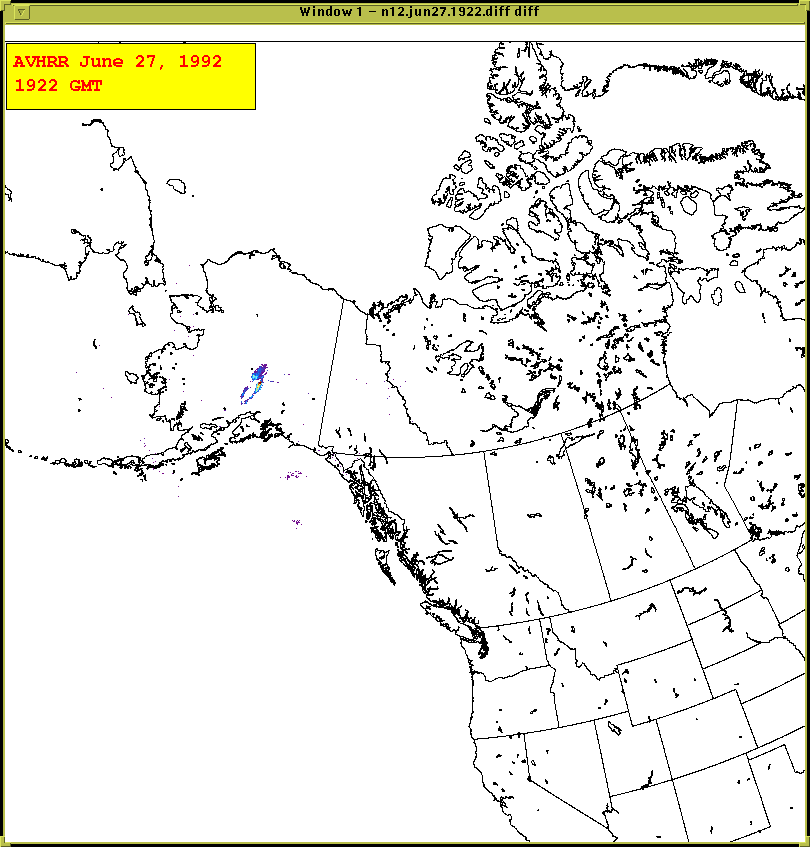
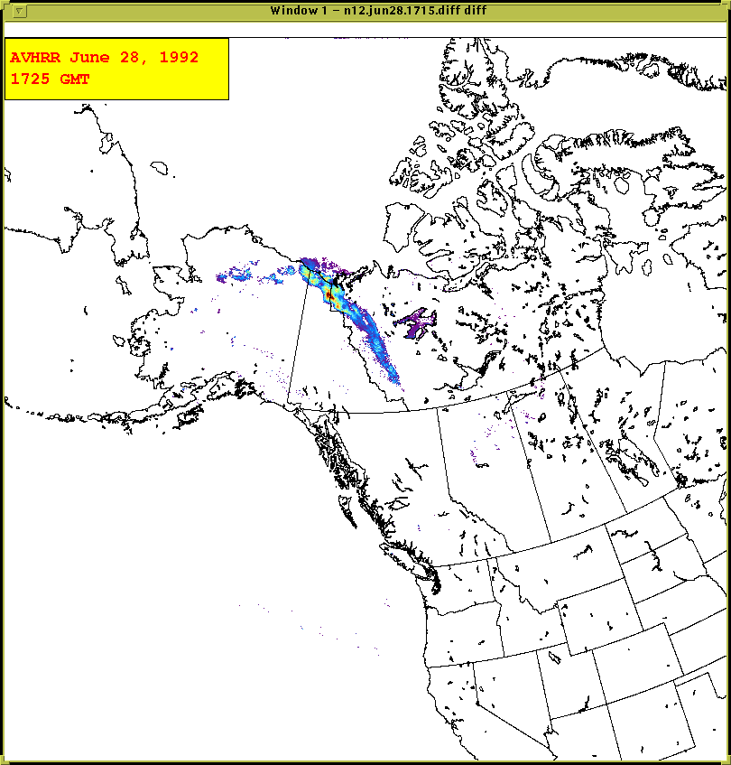
IIIi. TOMS detection sensitivity vs IR split window (Mt. Spurr, Alaska)
There are many opportunities for TOMS data to supplement that of IR sensors, such as AVHRR. Ultraviolet data, although coarser in scale, are less affected by background interferences such as temperature, and are able to discern ash clouds where IR methods cannot.
Dates/features to look for:
June 27, 1992: Compare the retrievals of the TOMS AI (1849 GMT) versus the AVHRR (1725 GMT). In this case the cloud is opaque to infrared in its central portion, but can be detected in ultraviolet channels. Of course, the TOMS spatial resolution (~50 km) is not nearly as good as the AVHRR (~1 km).
Select Load Related Data - ORBIT from level-2 daily file - 1992 - choose the daily file for day 179 - from the list, select s69057.
A new window appears with the file on it as your only choice. Click on that. Then once the file is loaded, Display it as always. Once you pull up the AVHRR image, you can zoom in on the TOMS image to make it roughly the same size for better comparison.
To pull up the corresponding AVHRR image, click here.
June 28, 1992: Compare the extents of the ash clouds as picked up by TOMS AI versus AVHRR. In the infrared the large changes in background temperatures (variations among snow/ice-covered land and water, versus open land and water).
Select Load Related Data - ORBIT from level-2 daily file - 1992 - choose the daily file for day 180 - from the list, select 69070.
A new window appears with the file on it as your only choice. Click on that. Then once the file is loaded, Display it as usual.
To look at the corresponding AVHRR image, click here.
References for Further Study
For more information, including TOMS image archives and publications, see the NASA TOMS SO2 web page, at http://skye.gsfc.nasa.gov/.
Bluth, G.J.S., W.I. Rose, I.E. Sprod, and A.J. Krueger (1997) Stratospheric loading from explosive volcanic eruptions. Journal of Geology, 105, 671-683.
Bluth, G.J.S., C.C. Schnetzler, A.J. Krueger, and L.S. Walter (1993) The contribution of explosive volcanism to global atmospheric sulphur dioxide concentrations. Nature, 366, 327-329.
Krotkov, N.A., A.J. Krueger, and P.K. Bhartia (1997) Ultraviolet optical model of volcanic clouds for remote sensing of ash and sulfur dioxide. Journal of Geophysical Research, 102, 21,981-21,904.
Krueger, A.J., L.S. Walter, P.K. Bhartia, C.C. Schnetzler, N.A. Krotkov, I. Sprod, and G.J.S. Bluth (1995) Volcanic sulfur dioxide measurements from the Total Ozone Mapping Spectrometer (TOMS) instruments. Journal of Geophysical Research, 100, 14,057-14,076.
Krueger, A.J., S. Schaefer, N. Krotkov, G. Bluth, and S. Barker (2000) Ultraviolet remote sensing of volcanic emissions and applications to aviation hazard mitigation. Geophysical Monograph Series 116, Remote Sensing of Active Volcanism, American Geophysical Union, 25-43.
McPeters, R., P.K. Bhartia, J. Herman, C. Wellemeyer, C. Seftor, G. Jaross, O. Torres, L. Moy, G. Labow, W. Byerly, S. Taylor, T. Swissler, and R. Cebula (1998) Earth Probe Total Ozone Mapping Spectrometer (TOMS) Data Product User's Guide. NASA/TP-1998-206895, Goddard Space Flight Center, National Aeronautics and Space Administration.
Rose, W.I., G.J.S. Bluth and G.G.J. Ernst (2000) Integrating retrievals of volcanic cloud characteristics from satellite remote sensors - a summary. Philosophical Transactions of Royal Society, Series A, v. 358, 1585-1606.
Appendix 1
TOMS-Observed Eruptions (Not a comprehensive list). Note: these days are for the start of the eruption, and actual TOMS detection might not have occurred until the following day.
|
Volcano |
Latitude |
Longitude |
Eruption Date |
Julian Date |
|---|---|---|---|---|
|
Cerro Azul |
-1 |
-91 |
November 29, 1979 |
333 |
|
Sierra Negra |
-1 |
-91 |
November 13, 1979 |
317 |
|
Nyamuragira |
-1 |
29 |
January 30, 1980 |
30 |
|
Mt. St. Helens |
46 |
-122 |
May 18, 1980 |
139 |
|
Hekla |
64 |
-20 |
August 17, 1980 |
230 |
|
Alaid |
51 |
156 |
April 27, 1981 |
117 |
|
Pagan |
18 |
146 |
May 15, 1981 |
135 |
|
Nyamuragira |
-1 |
29 |
December 25, 1981 |
359 |
|
El Chichon |
17 |
-93 |
March 28, 1982 |
87 |
|
El Chichon |
17 |
-93 |
April 4, 1982 |
94 |
|
Galunggung |
-7 |
108 |
April 5, 1982 |
95 |
|
Galunggung |
-7 |
108 |
May 17, 1982 |
137 |
|
Wolf |
0 |
91 |
August 28, 1982 |
240 |
|
Colo |
0 |
122 |
July 23, 1983 |
204 |
|
Mauna Loa |
19 |
-156 |
March 25, 1984 |
85 |
|
Fernandina |
0 |
-92 |
March 30, 1984 |
90 |
|
Krafla |
66 |
17 |
September 4, 1984 |
248 |
|
Nevado del Ruiz |
5 |
-75 |
September 11, 1985 |
254 |
|
Nevado del Ruiz |
5 |
-75 |
November 13, 1985 |
317 |
|
Nyamuragira |
-1 |
29 |
July 16, 1986 |
197 |
|
Chikurachki |
50 |
155 |
November 18, 1986 |
322 |
|
Chikurachki |
50 |
155 |
November 20, 1986 |
324 |
|
Fernandina |
0 |
-92 |
September 14, 1988 |
258 |
|
Redoubt |
60 |
-153 |
December 14, 1989 |
348 |
|
Mt. Pinatubo |
15 |
120 |
June 15, 1991 |
166 |
|
Cerro Hudson |
-46 |
-73 |
August 12, 1991 |
224 |
|
Mt. Spurr |
61 |
-152 |
June 27, 1992 |
179 |
|
Mt. Spurr |
61 |
-152 |
August 18, 1992 |
231 |
|
Mt. Spurr |
61 |
-152 |
September 17, 1992 |
261 |
|
Lascar |
-23 |
-68 |
March 19, 1993 |
109 |
|
Rabaul |
-4 |
152 |
September 19, 1994 |
262 |
|
Kliuchevskoi |
56 |
160 |
October 10, 1994 |
274 |
|
Soufriere Hills |
17 |
-62 |
December 26, 1997 |
360 |
|
Cerro Azul |
-1 |
-91 |
September 15, 1998 |
258 |
|
Nyamuragira |
-1 |
29 |
October 17, 1998 |
290 |
|
Shishaldin |
55 |
-164 |
April 19, 1999 |
109 |
|
Hekla |
64 |
-20 |
February 26, 2000 |
57 |
|
Miyakejima |
34 |
140 |
August 19, 2000 |
231 |
|
Nyamuragira |
-1 |
29 |
February 6, 2001 |
37 |
|
Reventador |
0 |
-78 |
November 3, 2002 |
307 |
|
Nyiragongo |
-1 |
29 |
May 3, 2003 |
123 |
|
Anatahan |
16 |
146 |
May 10, 2003 |
130 |